After all electronics for the Death Star where assembled test-wise, I wanted to create a „Lochraster“-layout. Unfortunately that’s not that easy with Fritzing.
Fritzing distinguishes only between breadboards and PCBs. You need to route Lochraster in the breadboard view. But the Lochraster-format is something in between as it needs routes on the copper-side of the board plus wires and components on the other. The breadboard only offers you one side for components and wires, but no copper-side routing.
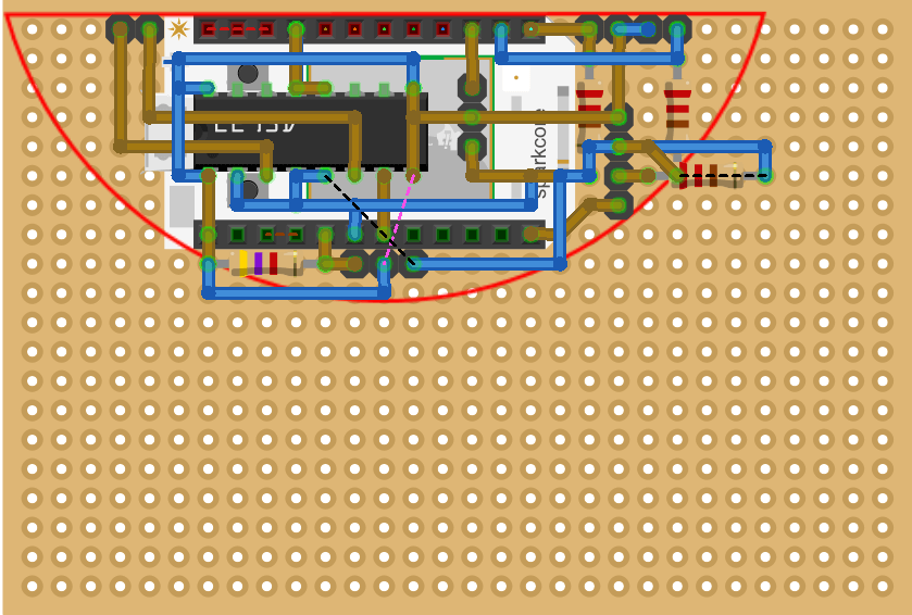
As a workaround I decided to use different colors for wires (blue) and copper-routes (ocker) to indicate the differences. For routes with vias to wires I didn’t find a solution. There is only one color per wire possible. Thus you need to keep in your mind, which wires are a route/wire-mix.
Second shortfall are resistors. Width and stand-up form factor are only visualized in the PCB view. Not in the breadboard. So you cannot layout them correctly.
These missing functionality makes the layout very complicated. But due to the small amount of components it should be still be possible to handle it.
BTW: The red line indicates the end-layout of the board, which will be the segment of an circle to fit into the lamp. I’ve created it as an image with the right size and than insert it into Fritzing as a picture.